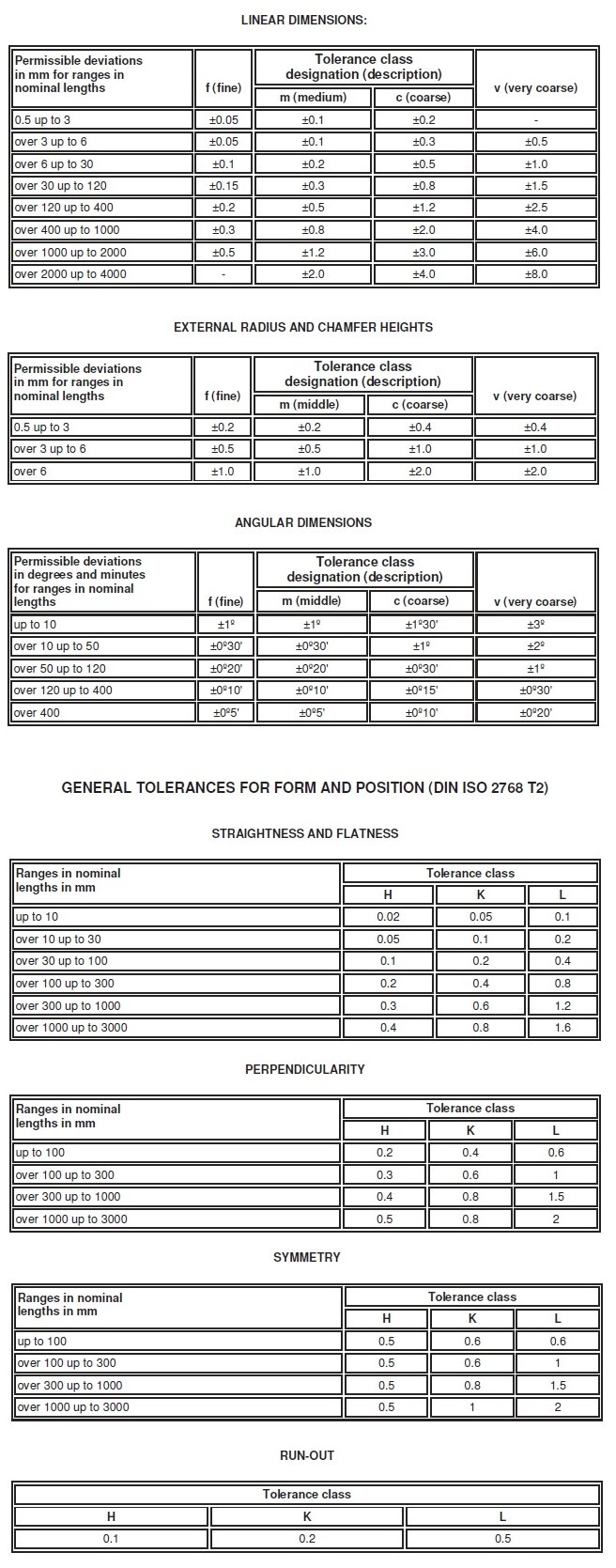
Iso 2768 Tolerance Table

Iso 2768 M Tolerances
Designation
Division of basic dimension 0.5 (1)
Over 3
Over 6
Over
Over
Over
Over
Over
up to 3
up to 6
up to
30 up
120 up
400 up
1000
2000
30
to 120
to 400
to
up to
up to
1000
2000
4000
Description
Permissible deviations f
fine
0.05
0.05
0.1
0.15
0.2
0.3
0.5
-
m
medium
0.1
0.1
0.2
0.3
0.5
0.8
1.2
2
c
coarse
0.2
0.3
0.5
0.8
1.2
2
3
4
v
very coarse
-
0.5
1
1.5
2.5
4
6
8
Note (1) :
For basic dimensions below 0.5 mm, the deviations shall be indicated adjacent to the relevant basic dimension(s).
Table 2. Permissible deviations for linear dimensions of chamfered parts (Rounding of corner and chamfered dimension) Unit : mm Tolerance class
Division of basic dimension
Designation
Description
0.5 (1)
Over 3
up to 3
up to 6
Over 6
Permissible deviations
Note (1) :
f
fine
m
medium
c
coarse
v
very coarse
0.2
0.5
1
0.4
1
2
For basic dimensions below 0.5 mm, the deviations shall be indicated adjacent to the relevant basic dimension(s).
Table 3. Permissible deviations for angular deviations
Tolerance class
Deviation of length (unit : mm) of the shorter side of the angle concerned Up to 10
Designation
Description
Over 10
Over 50
Over 120
up to 50
up to 120
up to 400
Over 400
Permissible deviations f
fine
m
medium
c v
1°
30c
20c
10c
5c
coarse
1°30c
1°
30c
15c
10c
very coarse
3°
2°
1°
30c
20c
Table 4. General tolerances on straightness and flatness Unit : mm Straightness and flatness tolerances for ranges of nominal lengths Tolerance
Up to 10
class
Over 10
Over 30
Over 100
Over 300
Over 1000
up to 30
up to 100
up to 300
up to 1000
up to 3000
General tolerances on straightness and flatness H
0.02
0.05
0.1
0.2
0.3
0.4
K
0.05
0.1
0.2
0.4
0.6
0.8
L
0.1
0.2
0.4
0.8
1.2
1.6
Table 5. General tolerances on perpendicularity Unit : mm Perpendicularity tolerances for ranges of nominal lengths of the shorter side Tolerance class
Up to 100
Over 100
Over 300
Over 1000
up to 300
up to 1000
up to 3000
General tolerances on perpendicularity H
0.2
0.3
0.4
0.5
K
0.4
0.6
0.8
1
L
0.6
1
1.5
2
Table 6. General tolerances on symmetry Unit : mm Symmetry tolerances for ranges of nominal length Tolerance
Up to 100
class
Over 100
Over 300
Over 1000
up to 300
up to 1000
up to 3000
General tolerances on symmetry H
0.5
K L
0.6 0.6
1
0.8
1
1.5
2
Table 7. General tolerances on circular run-out Unit : mm Tolerance class
Circular run-out tolerance
H
0.1
K
0.2
L
0.5

Iso 2768 Mk Tolerance Table
The preferred tolerances and fits advised by ISO and ANSI standards can be found in the 'Supplements' section. The tolerances defined in ISO 286-1 (2010) are applicable to size range from 0 mm to 3150 mm but there are a lot of exceptional cases defined in the standard which depend on tolerance selection. If general tolerances according to ISO 2768-1 are valid, the following has to be inserted in the title box, i.e. For tolerance class medium. ISO 2768 – m or general tolerance ISO 2768 – m. For new designs only the general tolerance according to DIN ISO 2768-1 should be valid. General Tolerances to DIN ISO 2768. The latest DIN standard sheet version applies to all parts made to DIN standards. Variations on dimensions without tolerance values are according to 'DIN ISO 2768- mk'. Iso 2768 Hole Tolerance Tables. Jdbc driver mysql. Joecool1964, While I agree that usage of term 'broken edges' in ISO 2768 is not fortunate, I also agree with CheckerHater - the standard specifically designated for edges of undefined shape is ISO. The purpose of Table 2 in ISO 2768-1 is to define tolerances for 'classic' chamfers and external radii. Doug, Just to add to what Steve has already mentioned: ISO 2768-1 General Tolerances (linear & angular) has three charts, Linear, Broken Edge & Angular. Each chart is divided in four classes of tolerances as follows: f = fine m = medium c = coarse v = very coarse The tolerance designation is determined by various items, such as size, complexity & means of manufacture of your parts. ISO 2768 and derivative geometrical tolerance standards are intendedto simplify drawing specifications for mechanical tolerances. ISO 2768 is mainly for parts that are manufactured by way of machining or removal of materials. DIN ISO 2768 mk tolerances I do not have a full copy of the DIN but I do have some notes and a brief discription of how the tolerances are supposed to work but I still dont quite understand it. Rc 20 vst crack. The parts are shafts and couplings and have to fit bearings so I know some of the tolerances are going to be plus and some are minus.